Solidworks Design Library Forming Tools
SolidWorks: Forming Tools
SolidWorks: Forming Tools
Over the years at Perception Engineering, I have modeled and detailed hundreds of sheet metal parts. Often these sheet metal parts will require specific tooling to match the customer specs. Taking to the internet for help on creating tooling yielded minimal results. Having to do my own research to ensure the customers receive the quality parts they requested; I've decided to post my finding to help others out.
Tooling Profiles
SolidWorks has included an assortment of default forming tools for sheet metal parts in the design library. Located on the left side of the SolidWorks interface, click on the Design Library dropdown to access the default forming tools.

Figure 1: Design Library
The forming tools can be applied to any sheet metal part by dragging the desired tool on the sheet metal part. For this, I chose the lance & form shovel. This feature can then be fully defined after the tool is dropped on the part.
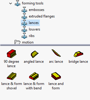
Figure 2: Forming Tools
The form tooling feature tree will open by default to move the tooling to the correct location. Most tooling positions can be easily adjusted by simply defining the center and rotation angle. If needed the tooling can be flipped too.
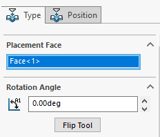
Figure 3: Tooling Feature Manager
In the Position tab shown in the figure above, the tooling can be fully defined and the option to add more tooling features can be done if more sketch points are added to the sheet metal part.
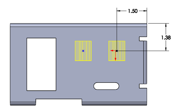
Figure 4: Defining Tooling
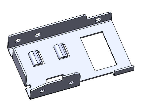
Figure 5: Tooling
Custom Tooling
At times other customers will require custom tooling. If the customer provid their custom tooling then simply drag and drop as shown above. However, most of the time Perception Engineering must make the tooling to match the customer profile. To do this, open a new part file.
Create a rectangle extrusion large enough to fit the tooling desired, this rectangle extrusion will later be deleted so don't spend too much time with getting a perfect size.
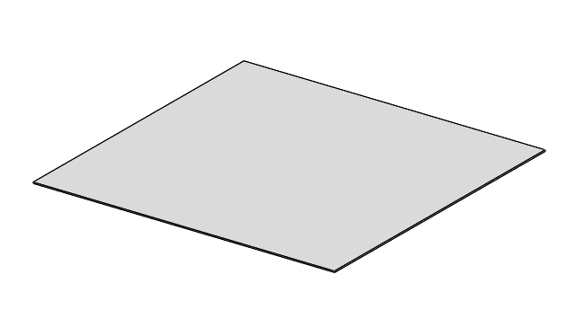
Figure 6: Custom Tooling Base
Now the custom tooling can be created as you would any other part: lofts, sweeps, extrusions, and fillets to create the customer stamping profile. Be sure that any radii on top of the tooling is smaller than the material thickness otherwise SolidWorks will not stamp the sheet metal.
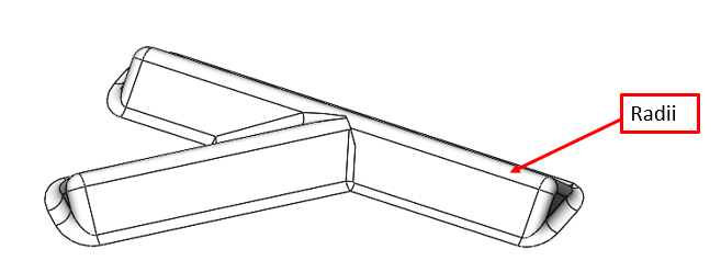
Figure 7: Modeling Tooling
The Form Tool can be found in one of two places: search Form Tool in the command search or by going to insert then sheet metal.
Tooling Profiles
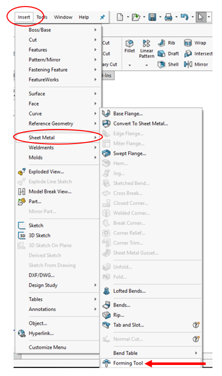
Figure 8: Forming Tool
The Form Tool Feature tree will pop-up and prompt you to select the stopping face. This will ensure the tooling will press up to the desired face forming the sheet metal as specified. Faces to remove will punch holes in the sheet metal with each face selected.
Once all the faces have been specified, the Insertion Point will need to be identified. This point similar to figure 4 will define the tooling within the sheet metal part.
The model can then be saved as a Form Tool File. Select File Save as and find Form Tool (*.sldftp) and be sure to save the file to the design library forming tools folder similar to the default tooling used ealier.

Figure 9: File Save as
The tooling is now successfully created! Go back to the sheet metal part that needs the tooling and find the tool. Place it on the sheet metal part and define the tooling location as you read above.
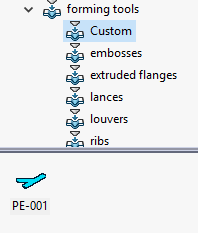
Figure 10: Custom Forming Tool
If you have any question, please feel free to contact me via LinkedIn. Thanks for reading the blog!
If you would like to learn more, check out these course that provide everything you need to know to get started!
Written By:

Brenden DeVries
Engineering Co-op at Perception Engineering
Solidworks Design Library Forming Tools
Source: https://www.perceptioneng.com/blogold/2018/7/12/solidworks-forming-tools
Posted by: hansoneachich.blogspot.com

0 Response to "Solidworks Design Library Forming Tools"
Post a Comment